Advanced Force Network Support in InfoSewer for Steady State and EPS
Advanced Force Network Support in InfoSewer for Steady State and EPS
- EPS and Steady State FM Options

- Simulation Options for the Advanced ForceMain Network Support

The Advanced Force Network Support allows the simulation of multiple upstream and downstream force mains entering and leaving one chamber junction during an Extended Period Dynamic Simulation or EPS solution in Sewer. All of the force mains, pumps, wet wells and force main chamber junctions that are connected are considered as one force main network in the EPS and steady state solution. You can have more than one force main network in a large Sewer model separated by gravity pipes and loading manholes. The individual force main networks are solved iteratively with different upstream head and downstream tail manholes which connect the force main network(s) to the rest of the network.
A force main network consists of the following elements:
· Wet well
· Pump
· Junction Chamber
· Head Manhole where flow from other parts of the sewer system enters the force main network or loading manhole
· Tail manhole where the flow leaves the force main network.![SNAGHTML16139c80[19]](https://lh3.googleusercontent.com/blogger_img_proxy/AEn0k_vNu6jI8CDhGBP0JHWztq1jcxHYqhtXTroQHWBivKpQs_XNpAXdjnj3pu23gb6AfyZgyAldTWhK4zIrEc88bJMZMDSo7ifyvcthVkp9ADqj0eZQrBBHENWBDxv8gIGHCvy-3Cl7YNMjbA=s0-d "SNAGHTML16139c80[19]")
![SNAGHTML16139c80[19]](http://swmm5.files.wordpress.com/2015/08/snaghtml16139c8019.png "SNAGHTML16139c80[19]")
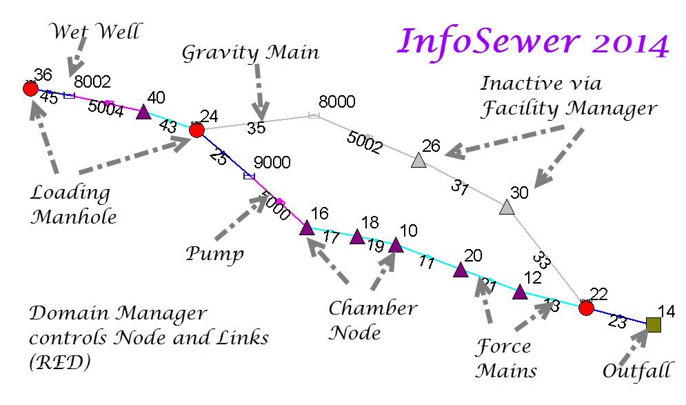
- Elements in InfoSewer
The head and tail manhole for one force main network is determined by the program based on the geometry of the network. The force main network starts at a wet well, includes the pumps connecting the wet well to the force main links and also includes the actual force main links and force main connecting junction chambers. You can also connect a force main to the gravity mains without an intermediate wet well and pump(s).
The boundary conditions of the force main network are:
· Water heads at the wet wells which vary according to the inflow from the upstream sections of the sewer network and outflow to the force main network
· Water head at the tail manholes which are calculated as the maximum discharge head (invert + diameter) of all the force mains that end at that manhole. Water entering the tail manholes will be routed downstream after the force main network flows are calculated.

- An Example of how Newton Raphson Solves for Zero
For example, assuming there are n1 wet wells, n2 head manholes, n3 tail manholes, n4 junction chambers and l1 pumps and l2 force mains, the program must solve the network hydraulics to get n2+n4 water head values and l1+l2 flow values iteratively using the Newton-Raphson method. The solution iterates until the mass and energy of the force main network is in balance.
The hydraulic equations used in the solution are:
· Head/Flow relationship of the force mains and pumps (l1+l2 equations)
· Mass balance at head nodes and junction chambers (n2+n4 equations)
For head nodes, water entering the network from other sections of the sewer system must equal the flow sum of force mains that connect to it:

Where Q = Flow; Gv = group of gravity pipes connecting to the head manhole; and Gf = group of force mains connecting to the head manhole. The sum of the gravity flow into the wet well or head manholes is balanced by the sum or flow out of the force main network in the force main pipes.
For junction chambers, which are connected to only force main pipes:
![SNAGHTML16495507[16]](http://swmm5.files.wordpress.com/2015/08/snaghtml1649550716.png "SNAGHTML16495507[16]")
For force mains, Hazen-Williams equation describes the flow/head loss relationship within a force main. The flow out of and the flow into the junction chamber is in balance. The head at the junction manhole is iterated until the flows are in balance.
For pumps that are neither Inflow Control nor Discharge Control,  the pump curve is used to estimate the flow and head gain relationship within a pump. For Inflow Control and Discharge Control pump, pump flow as control values are fixed and the equation Q = Qcontrol, where Qcontrol is the controlling pump value. For such situations, the pump is actually modeled as variable speed pump and pump speed will be calculated with Newton-Raphson method to achieve the flow control objective.
 the pump curve is used to estimate the flow and head gain relationship within a pump. For Inflow Control and Discharge Control pump, pump flow as control values are fixed and the equation Q = Qcontrol, where Qcontrol is the controlling pump value. For such situations, the pump is actually modeled as variable speed pump and pump speed will be calculated with Newton-Raphson method to achieve the flow control objective.
- Pump Curve Example in H2OMap Sewer or InfoSewer


Comments
Post a Comment