Posts

Showing posts from September, 2016

How to Make Break Nodes in #INFOSWMM and #H2OMAP SWMM
Image
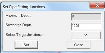
How to Make Break Nodes in #INFOSWMM and #H2OMAP SWMM You would add a break node to break up long force mains so that the pipe(s) react faster to the pump flows. Find your long FM or long  Gravity Main links Insert a Node into the middle of the link to break the link into two links with the same geometry but different lengths Use the Node Inference tool to estimate the new nodes invert based on the immediate upstream and downstream node inverts   If you make a new for a FM, please also use this tool   which will set the Surcharge depth – 1000 is bit high .  Steps used to Insert Nodes in a Force Main

InfoSWMM and the Custom Report Tool

Image
Step 0 is to define the domain and use the Custom tool in Tools, Step 1 is to define the data source Step 2 is to define the fields to show in the table Step 3 is to define the source (click on Domain) and Step 4 is to view the output table.

Larger Fonts in #SWMM5 using Delphi

Image
If you Delphi XE2 to XE7 then it is easy to adjust the Fonts in Fmain.pas using the Respective Property Pages - it does not work for menus, unfortunately.

The Impact of the yCrown Taper equation in #SWMM5 on Surcharged Nodes

Image
The Impact of the yCrown Taper equation in #SWMM5 We are looking at three ranges of depth in the node: 1.  Node depths below yCrown using the node continuity equation to compute the new node depth, 2. Node Depths above 1.25 * yCrown use the point iteration solution for the node in which there is no node area and the program iterates until the sum of flows is zero for the timestep. 3.  Node Depths between yCrown and 1.25 * yCrown use the taper equation in which the node area decreases from the area at 0.96 Full Depth to a value of zero area at 1.25 yCrown. If the current depth in the node is below 1.25 * yCrown Where,  yCrown is the depth till the highest connecting conduit crown elevation There is a tapered equation based on the sum of the  flow at the node and the surface area from the last non-surcharged condition which will influence dqdh if depth close to crown depth F = yLast/yCrown – 1 Denom = Sum DQDH for all connecting links to the node Denom = Denom + (Old Surface Area (at la

Spatial Databases in #InfoSWMM and #InfoSewer using ArcCatalog™

Image
Spatial Databases in #InfoSWMM and #InfoSewer using ArcCatalog™ With ArcCatalog™ , you can explore and manage geographic data stored in an RDBMS through ArcSDE™ . Similarly, SDE for Coverages lets you access coverage, ArcInfo™ LIBRARIAN, and ArcStorm™ databases the same way you access data from an RDBMS. To access these spatial databases, you must add a spatial database connection to the Catalog. Refer to the section on   Database Connections folder -> Spatial Database Connection   link in the ArcGIS help file to learn more.

Pump as a Node In Water and System Head Curve

Image
System Head Curve Note:  This is a feature often asked for in InfoSWMM and SWMM5.  Pumps are links in the SWMM5 engine. The dialog box for system head curve is shown below. Click   here   for the methodology of system head curve. Input for system head curve: •   Flow Unit   – Select the desired flow unit. •   Head Loss Equation   – Select from Manning, Darcy-Weisbach (Colebrook-White), or Hazen–Williams formula. •   Pipe 1   – The pipe that connects the upstream reservoir with the pump (i.e., pipe on the suction side of the pump). •   Pipe 2   – The pipe that connects the pump with the downstream reservoir (i.e., pipe on the discharge side of the pump). •   Coefficient   – Roughness coefficient. •   Head at Position 1   – Head at the upstream reservoir. •   Head at Position 2   – Head at the downstream reservoir. •   Length   – Length of the pipe (i.e., pipe 1 or pipe 2). •   Diameter   – Diameter of the pipe (i.e., pipe 1 or pipe 2). •   Sum of Minor Loss Coefficients   – Sum

#SWMM6 - A Sustainable Center for Crowd-Sourced Water Infrastructure Modeling

Image
#SWMM6 - A Sustainable Center for Crowd-Sourced Water Infrastructure Modeling https://t.co/3YuI73JSuf pic.twitter.com/iEVrIxCYSH — Robert E Dickinson (@RDickinson) September 26, 2016

How to add a new view variable to SWMM 5.1.011

Image
How to add a new view variable to SWMM 5.1.011 If you want to add a new view variable to the graphs of SWMM 5 – this is the steps you have to take (3 in the Delphi GUI and 3 in the SWMM 5 C Engine code). This example will add a new view variable called NodeXTRA at the end of the Node list of view variables (Figure 1).  You add it to three locations in the Delphi XE7 code (Figure 3) and three locations in the SWMM 5 Engine code (Figure 3).  The purpose of this note is for students and as a reminder to myself. Figure 1 - New view variable called NodeXtra Figure 2 - We need to make a few additions to the Delphi GUI code to see the Name NodeXtra when we run SWMM 5.1.011 Figure 3 - SWMM 5 C code - We need to add the NodeXtra variable to the code to see some numbers and results.

How to Add Extra Output Files to SWMM 5.1.011

Image
How to Add Extra Output Files to #SWMM 5.1.011 – the goal here is to automatically make calibration files for InfoSWMM, H2OMap SWMM, SWMM 5 and other programs based on the name of the Outflows file in SWMM 5. Step 1.   Add names to globals.h EXTERN TFile                   Finp,                     // Input file                   Fout,                     // Output file                   Frpt,                     // Report file                   Fclimate,                 // Climate file                   Frain,                    // Rainfall file                   Frunoff,                  // Runoff file                   Frdii,                    // RDII inflow file                   Fhotstart1,               // Hot start input file                   Fhotstart2,               // Hot start output file                   Finflows,                 // Inflows routing file                   Foutflows,                // Outflows routing file                   FcalibrationS,